> For the complete documentation index, see [llms.txt](https://docs.jcore.io/clarity-gateway/llms.txt). Markdown versions of documentation pages are available by appending `.md` to page URLs; this page is available as [Markdown](https://docs.jcore.io/clarity-gateway/connections/local-i-o/configuring-digital-outputs.md).
# Configuring Digital Outputs
To make a Local I/O Channel operate as a digital output, first click the channel in the sidebar to go to the channel settings view:
Then click **Digital Output** in the view that appears:
Finally, click **Save**:
### Control Mode: Output a Tag
After the preceeding steps, we've configured Channel 1 to output a tag, but the configured tag (**channel1**) doesn't currently have a value (**Control Value: NA**), so the configured **Safe State** is being sent to the output:
This is because there's currently no source for the **channel1** tag, which is why Clarity Gateway reports **There is currently 1 mapping problem:**
If you click that link you'll see that **channel1** is listed under **Output Tags with no source** in the mapping problems view:
If you change the **Safe State** to **Output On** and click **Save**, the **Safe State** and **Raw Output** will change to **1**:
Let's configure Channel 1 to output the **channel2** tag, which is currently being set from Channel 2, which is configured as a digital input in this example. Go back to the settings for Channel 1 and change **Tag** to **channel2**:
Then click **Save**. After you do, you should see the arrow leading from the **Control Value** to the **Raw Output,** and **Raw Output** should have the same value as **Control Value**, which corresponds to the state of Channel 2 in the sidebar:
You can also output values coming from other sources like Modbus, MQTT, and EtherNet/IP connections by setting the **Tag** to a connection channel's configured **System Tag**.
### Control Mode: Condition
This control mode allows you to use boolean logic on other tags to control the output value. For example, let's say **channel2** is a digital input, **channel3** is an analog input, and we want to output **1** when **channel2** is **1** or **channel3** is **> 5**.
First make sure **Tag** is **channel1**. The value determined by the condition will be written to this tag:
Then change the **Control Mode** to **Condition**:
In the **Control Logic** table that appears, click **Add Condition**:
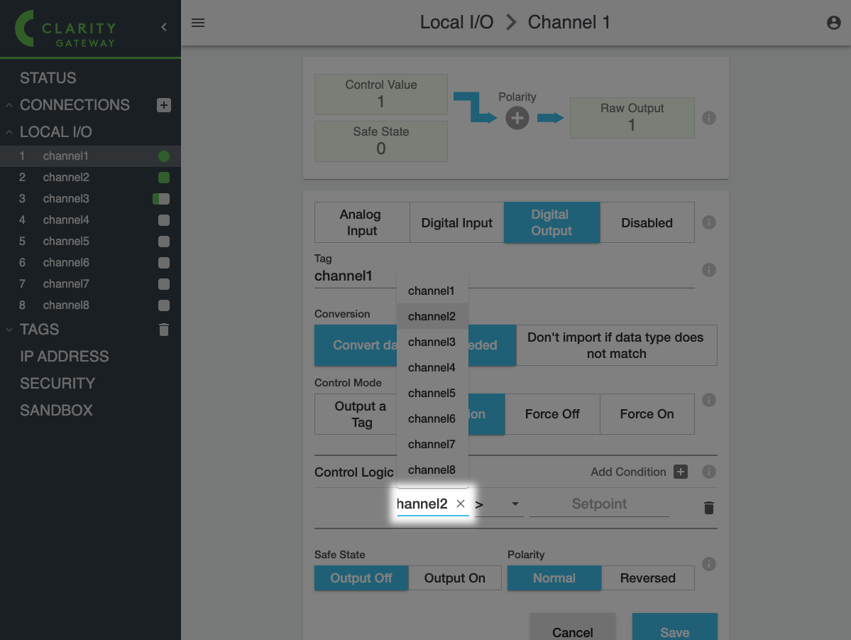
In the row that appears below, enter **channel2** for the tag:
And **= 1** in the following fields:
Now we need to add the condition for **channel3**. Click **Add Condition** again:
In the second row will appear with an **AND** operator:
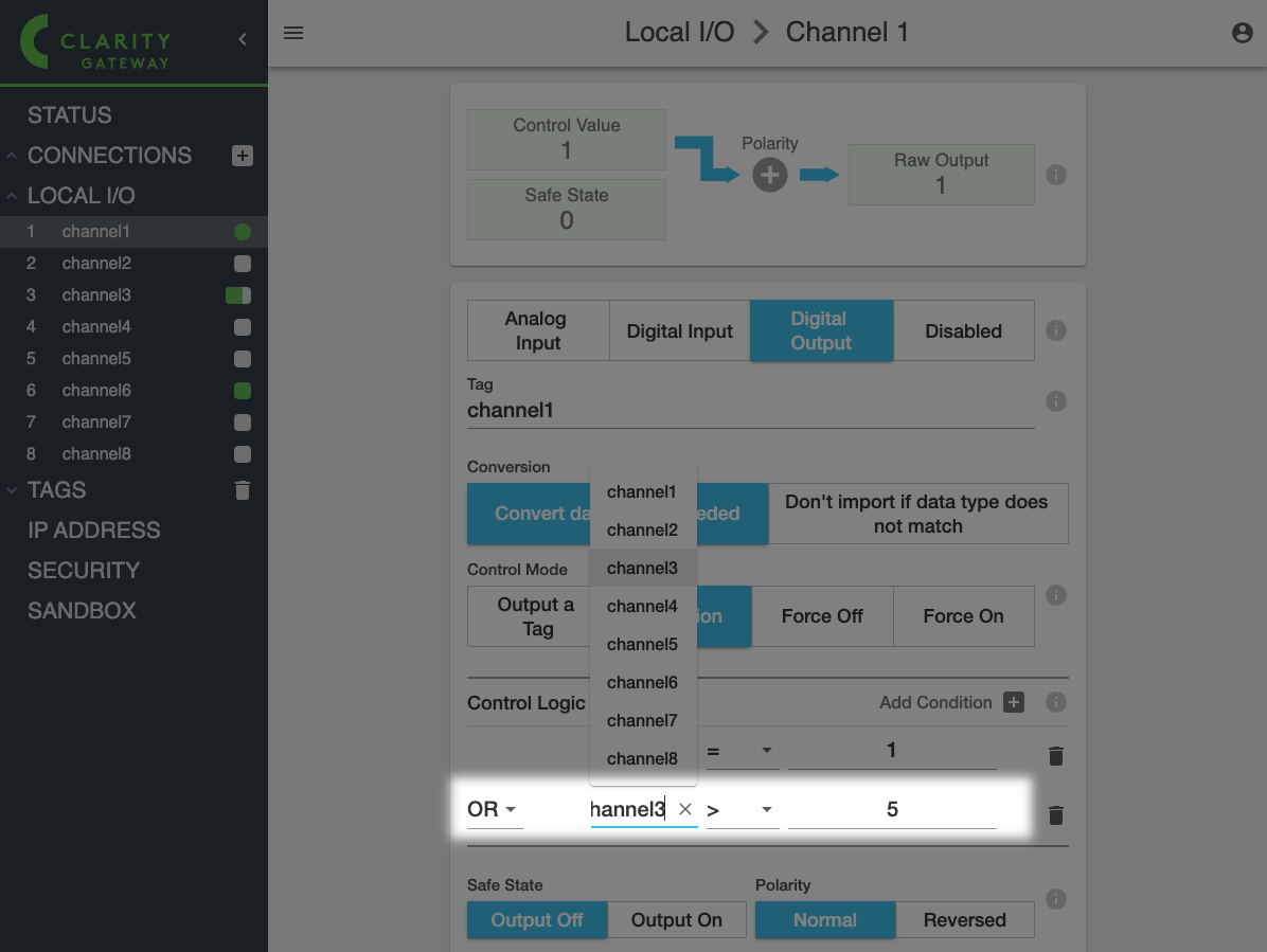
Change this to **OR**, and enter **channel3 > 5** in the following fields:
Finally, click **Save**:
The following screenshots show how the **Control Value** and **Raw Output** now apply this control logic:
channel2 = 0, channel3 <= 5
channel2 = 1
channel3 > 5
### Control Mode: Force Off/Force On
These modes force the **Control** **Value** to be **0** or **1** and don't read or write any tags.
Note that **Reversed Polarity** can still cause the **Raw Output** to be the opposite of the **Control Value**:
.png?alt=media)
.png?alt=media)
.png?alt=media)
.png?alt=media)
.png?alt=media)
.png?alt=media)
.png?alt=media)
.png?alt=media)
.png?alt=media)
.png?alt=media)
.png?alt=media)
.png?alt=media)
.png?alt=media)
.png?alt=media)
.png?alt=media)
.png?alt=media)
.png?alt=media)
.png?alt=media)
.png?alt=media)
.png?alt=media)
.png?alt=media)
.png?alt=media)